

Tribofilm Growth: How Contact Stress and Film Removal Work Together
How a protective film can grow and wear at the same time
When lubrication is too thin to keep opposing surfaces completely apart, microscopic contacts must survive repeated loading and sliding. Anti-wear additives can help by forming a protective reaction layer, called a tribofilm. The layer is not simply deposited once and left unchanged: it can grow, deform and be removed while the underlying component continues operating.
This raises an important modelling question. Why does film thickness sometimes approach a steady value rather than increase indefinitely? Temperature influences chemical reactions, but the contact stresses also change as a comparatively compliant film develops on a harder substrate. A useful explanation must connect those mechanical changes with both growth and removal.
Akchurin and Bosman addressed that coupling in a 2017 study of zinc dialkyldithiophosphate, commonly called ZDDP. Their work belongs to TriboSolver’s research history. The tribofilm-growth model described here is not offered as a current TriboSolver product capability. The article explains the published method and its limits, rather than providing a current-software tutorial.
The investigated systems
The authors compared their model with previously published experiments at two scales. The microscopic case used a silicon AFM tip carrying a 15 nm diamond-like-carbon coating, against a silicon substrate carrying a 10 nm iron coating. The tip radius was 53 nm. Calculations considered loads of 600 and 340 nN, and film growth was assumed to occur on the iron-coated substrate.
The macroscopic comparison concerned rough steel contacts at 60 N, an entrainment speed of 0.1 m/s and a slide-to-roll ratio of 5%. Film-thickness measurements were available at 60, 80 and 100 °C. Entrainment describes the motion carrying lubricant through a contact; slide-to-roll ratio expresses the relative sliding component. These conditions should not be transferred to the microscopic AFM case.
The paper’s abstract describes a steel ball and disk, while Table 1 labels the curved body “Cylinder.” That table gives a 19.05 mm curvature radius and a flat counterbody. This terminology inconsistency should be resolved against the original experimental description before attempting an exact reconstruction; it does not justify silently choosing a different geometry.
Why a numerical contact model was needed
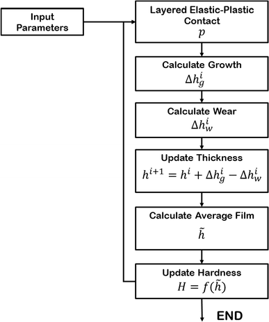
A growing film changes the interface that generates the stress driving its growth. Treating pressure as a fixed input would miss that feedback. The authors therefore recalculated the contact as thickness and mechanical response evolved. A layered model was needed because a thin, compliant film and its supporting substrate do not respond like one homogeneous bulk material.
The calculation enforced load balance and a hardness limit on local pressure. It supplied pressure and deformation, not a complete molecular description of ZDDP chemistry. The growth and removal laws supplied the additional relationships needed to predict a thickness history.
How TriboSolver’s predecessor was used
The publication’s reference 26 identifies Tribology Simulator and links to its TriboNet software page. The contact component used an elastic–fully-plastic boundary element formulation with a half-space approximation. A discrete-convolution/fast-Fourier-transform technique evaluated deformation, including influence terms for normal and tangential loading.
| Model element | Information used in the study |
|---|---|
| Contact bodies | Microscale: DLC-coated AFM tip and iron-coated substrate. Macroscale: rough steel bodies. |
| Geometry | AFM tip radius 53 nm. Macroscale Table 1 curvature radius 19.05 mm against a flat; ball/cylinder terminology differs between abstract and table. |
| Normal load | 600 and 340 nN for microscopic comparisons; 60 N for macroscopic comparisons. |
| Surface input | Macroscopic RMS roughness 20 and 130 nm in Table 1. Exact supplied height arrays and numerical grid: not reported in the accessible source. |
| Material properties | Steel bodies: E = 210 GPa, ν = 0.3, H = 6 GPa. Microscopic film calculation used E = 15 GPa and constant H = 2 GPa; macroscopic film hardness followed an empirical thickness/temperature relationship. |
| Contact model | Layered elastic–fully-plastic BEM, half-space approximation, pressure cutoff and FFT-based deformation evaluation. |
| Main contact outputs | Contact-pressure distribution and deformation; shear stress estimated using constant friction coefficient 0.1. |
| Coupled models | Stress-activated Arrhenius growth; thickness-proportional film removal; updated mean layer thickness and hardness; calibrated substrate-loss relationship. |
The feedback loop: contact, chemistry and removal
The algorithm began without a tribofilm. It calculated contact pressure and estimated shear stress from pressure multiplied by the assumed friction coefficient. A stress-activated reaction law then determined local growth. In physical terms, the model relates reaction rate to temperature and the influence of stress on an activation barrier.
Removal was proportional to the film thickness through a fitted coefficient. Net thickness change was growth minus removal. The model then averaged the updated thickness and treated that average as a uniform layer for the next contact calculation. This simplification retains mechanical feedback without explicitly representing every aspect of a patchy chemical film.
The activation energy, activation volume and removal coefficient were calibrated using experiments. For the microscopic model, Table 2 reports activation energy 0.8 eV and activation volume 85 ų; the macroscopic fit used 0.665 eV and 53 ų. These are fitted model parameters, not universal constants for all oils, additive concentrations or substrates.
What the comparisons showed
In the initial AFM calculation, growth of a softer layer reduced mean pressure. Nevertheless, pressure stayed high enough for growth to continue. Stress relaxation alone did not reproduce the observed self-limiting behavior. Including film removal allowed the calculation to approach a steady thickness through a balance of competing rates.
A transient thickness overshoot required an additional delay in the removal law. The earliest nucleation stage still was not reproduced. At 340 nN, the model used the same input parameters as the higher-load case, but the corresponding experiment stopped before saturation. That comparison therefore supports the observed growth interval, not a measured final thickness at the lower load.
The macroscopic calculations reproduced temperature-dependent thickness trends after fitting a shared parameter set. The authors separately related film removal to loss of substrate atoms using a concentration that decreased with film thickness. Film loss and component wear were thus different quantities, not interchangeable outputs.
| Temperature | Measured depth increase | Calculated depth increase |
|---|---|---|
| 60 °C | 85 nm | 86.3 nm |
| 100 °C | 45.4 nm | 45.8 nm |
These Table 3 values are differences between measurements at 45 and 120 minutes, not wear from a pristine surface over the whole test. The concentration parameter was fitted to these data. Close agreement therefore demonstrates the calibrated comparison; it is not an independent blind validation or a new verification run performed for this note.
What TriboSolver contributed—and what it did not
Contact solver contribution: layered pressure and deformation calculations updated as the modelled film evolved.
Additional coupled physics: calibrated reaction kinetics, film removal, empirical hardness evolution and substrate-concentration-based wear.
Not demonstrated: parameter-free additive design, complete nucleation chemistry, general prediction for every lubricant, or availability of this research model in the current TriboSolver release.
The constant friction coefficient, uniform effective layer and empirical hardness law limit interpretation. The authors estimated frictional heating below 1 °C for their cases and neglected it; other conditions require a new check. Exact height maps, numerical tolerances and the historical executable were not supplied here as a reproducibility package.
Practical relevance and conclusion
The workflow could help structure future research on boundary-lubricated contacts: measure film evolution, characterize layer mechanics, calibrate chemistry and test predictions under additional conditions. Bearings or gears would require geometry, lubricant and operating data appropriate to those applications. The paper does not validate every such extension.
The central lesson is that protective-film thickness emerges from interacting processes. Contact mechanics changes the stress; stress and temperature influence growth; removal opposes it. This historical model illustrates how a contact calculation can support a larger research workflow, while also showing why fitting requirements and missing physics must remain visible.
Reference and software links
Aydar Akchurin and Rob Bosman. “A Deterministic Stress-Activated Model for Tribo-Film Growth and Wear Simulation.” Tribology Letters 65, 59 (2017). Open-access canonical article · Published PDF.
Explore current TriboSolver access options or discuss your application. These links do not imply that the tribofilm model is included in the current product.